Google
Showing posts with label Turbo. Show all posts

Saturday, October 18, 2008

My turbo fitting

Take such long time to finish my turbo . I haven't finish it yet . Just got my turbo fitting for engine oil inlet , water inlet and outlet . Soon will remove oil sump to make fitting for oil drain . Below is picture of fitting for my turbo . Thanks lip teik from hydraulic shop in kepala batas penang . With his help , i can get those nice fitting easily . No need any hassle modification .


Saturday, May 3, 2008

TURBO BASIC

By TURBO TORQUE - www.mazdarotary.net


Turbo Basics

A turbocharger is used to force air/fuel mixture into an engine at a pressure greater then the natural atmospheric pressure of around 14.5 PSI. When a turbo produces 7 PSI of boost, this means how much extra pressure it applies on top of the natural atmospheric pressure. The way a turbo works is the exhaust coming out of the engine is pushed through a turbine. This turbine is mounted on a shaft, which in turn spins an air compressor. The compressor draws air in and blows it into the inlet manifold, and this produces BOOST. The whole point of forcing the air/fuel mixture into an engine is to allow it to burn more fuel and make more power with the same engine capacity. This can get complicated, as there are several factors that get in the way of efficency gain. For one thing when you compress air (with a turbo) it gets hotter. The problem with hotter air is that it contains less oxygen than cooler air, so there is less oxygen to help burn extra fuel that’s going into the engine. This is why many turbocharged cars use “intercooling” of various types, to cool the pressurised air back down into the engine.

Compressed Air = Hot Air

It’s important to consider problem of too much heat inside the engine. Once the hot compressed air goes inside the engine it is then compressed again by the piston in the engine. Therefore by the time the mixture of fuel/air mixture is ignited it is really hot. When it is too hot it could ignite itself before the spark plugs fires (known as pinging). When the engine pings the smooth, well-timed normal ignition mishaps, costing you power and damaging ports to the engine. Damage is caused to the engine, and can therefore lead to blowing the head gasket, this then chain-reacts to more severe cases. Another problem when the engine has an air/fuel mixture which is too lean, that is not enough fuel for the air coming in, which creates too much heat, or having ignition which is not suited to the engine. With private turbo installations these problems are often ignored. The ignition timing required for optimum power and smoothness from a turbocharged engine is in fact totally different to that required for a non-turbo engine. This is because the more efficient the engine is, the less advanced the ignition timing needs to be to get power combustion of the fuel/air mixture. When the engine gets more and more boost, the ignition should happen later and later in each cylinders or rotors combustion cycle. To get best out of the turbocharged engine it needs a balance of boost, mixture richness, charge air temp and ignition timing that allows it to run smoothly and efficiently with the type of fuel you're using. If you use low-octane fuel, it is more susceptible to pinging as it ignites more suddenly and erratically. The higher the octane of your fuel, the more smoothly and progressively it will burn, which helps prevent pinging. This means that with better fuel you can run more boost or more advanced ignition without any engine difficulties, which indeed means more POWER.


Turbo Engine Setups

Carburetor

There are two types of choices in a carburetor turbo setup: “Suck-through” or “Blow through”. The Suck-through (or draw through) setup involves mounting the carburetor before the turbo inlet (usually in front of the impeller mouth). This means that both fuel and air are drawn into the turbo already mixed and then blown into the inlet manifold. This is by far the simplest way to set up a turbo, as the carburetor doesn’t need to be especially modified and tuning is quite easy. The main disadvantages are that you can’t use any intercooling with such a setup, as it is dangerous to run air/fuel mixture through an intercooler core. The reason for this is that fuel can condense inside the intercooler core and stay there – if you then have an engine backfire the intercooler can explode. As a result water injection is about the only option for cooling the charge air with this setup. This also corresponds to a blow-off valve because instead of just venting pressurised air, it would be releasing a fuel/air mixture which is very dangerous. The Blow-through arrangement, logically enough, means the carburetor is mounted after the turbo compressor, so the turbo only draws in air and then blows it through the carburettor, which adds the fuel. To use a carburetor this way it has to be specially modified so that the jets will still add the right amount of fuel. This means specially sealing the carburetor and pressurizing the fuel bowls to match the turbo boost. The good thing is than an intercooler and also a blow-off valve can be used with such a setup.

Fuel Injection

Fuel Injection is the best setup for a turbo engine. As the injectors are controlled by a computer you have full control over the fuel delivery and can tune the engine’s fuel/air ratios much more accurately rather than with jets. A turbo charged EFI engine would have an air filter before the turbo, which then blows through a pipe to the throttle body. The throttle body controls how much air goes into the inlet manifold, which is where the injectors add the fuel. The intercooler (if fitted) is mounted after the turbo, but before the throttle body. When adding a turbo to a naturally aspirated EFI engine, more often then not the injectors themselves will have to be upsized to cope with the fuel demands of a turbo charged engine. The smaller injectors will fail to keep up with the engine and cause it to lean out. Likewise the fuel pumps will often need to be upgraded, because its no good having big injectors if the fuel pump can't keep the fuel pressure up to them at high RPM. Rather than designing a new fuel map and changing the factory injectors, an independent injector driver can be used to drive one or more extra injectors. This is cheaper and easier to do, so it is quite popular for cheaper turbo kits and upgrades. However, it does not offer the same degree of fine-tuning as complete fuel system upgrade. For the best drivability and reliability a full after market programmable computer system is definitely the way to go. Using a programmable computer also gives you much more flexibility for making future modifications.

Twin Turbo

Factory twin turbo systems are invariably designed to make the engine more tractable, rather than more powerful. To understand why this is so, you have to realise that big turbos and small turbos behave quite differently. A small turbo has minimal inertia, so it takes more gas flow and boost. On the other hand a small turbo may not be able to flow boost up to a maximum level when a large engine is revving to its greatest. A larger turbo will have greater further capacity, so although it takes longer to speed up, it wont run out of puff at the top end of an engines rev range. To give an example say we have a 2.0 litre engine with a small turbo like a Garret T2. Such an engine would come “on boost “ at very low engine speeds possibly before below 2000RPM, but due to the limited flow capacity of the turbo, by 4000RPM boost would start to trail off and by 6000RPM you might have less then half your normal boost level. If you change this turbo for something very large like a Garret T4, the engine wouldn’t come on boost until much later – probably around 4000RPM, which may make the car a bit difficult to drive, but the good thing is that by 6000RPM the turbo would still happily provide full boost. Normally you would look for a compromise somewhere in between, like a T28, so you would get boost just before 3000RPM and only trail of very slightly at the top end. Ready to get the best of both turbos, however, some manufacturers have used a set up called “sequential turbo charging”. Put simply, this system uses a small turbo to give boost at low RPM, with an additional larger turbo kicking in at higher RPM. These systems take a lot of development to get working smoothly and are also expensive to do in an aftermarket engine, but factory sequential turbo engines like the 13B-REW rotary in the series 6 RX7 are certainly very impressive. A slightly simpler approach is to use two small turbos instead of one big one. This way both turbos come on boost at relatively low RPM, but because you have twice the flow of one small turbo, boost doesn’t tend to drop off at higher RPM quite as much. For ultimate power potential, however, one big turbo still has more potential due to superior to its flow efficiency. This is why drag cars generally use one huge turbo even if the engine came with a twin turbo setup originally.

High Flow Turbos

Turbo sizes need to be properly calculated to get optimum performance and drivability for a given engine. Generally a hi-flow turbo will use the existing exhaust turbine from a factory turbo, with either a larger compressor wheel in the existing housing, or a whole new compressor assembly grafted on. It is generally the case that the existing turbines on factory turbochargers can support a larger compressor, so this is convenient way to improve the flow capability of your turbocharger while still keeping the original manifolding, oil feeds and etc. This process is relatively cheaper than going for a new turbo and associated parts required for that turbo.

Tuesday, April 8, 2008

ALL about turbo exhaust manifold - DSM

N/A cars: As most of you know, the design of turbo exhaust systems runs counter to exhaust design for n/a vehicles. N/A cars utilize exhaust velocity (not backpressure) in the collector to aid in scavenging other cylinders during the blowdown process. It just so happens that to get the appropriate velocity, you have to squeeze down the diameter of the discharge of the collector (aka the exhaust), which also induces backpressure. The backpressure is an undesirable byproduct of the desire to have a certain degree of exhaust velocity. Go too big, and you lose velocity and its associated beneficial scavenging effect. Too small and the backpressure skyrockets, more than offsetting any gain made by scavenging. There is a happy medium here.

For turbo cars, you throw all that out the window. You want the exhaust velocity to be high upstream of the turbine (i.e. in the header). You'll notice that primaries of turbo headers are smaller diameter than those of an n/a car of two-thirds the horsepower. The idea is to get the exhaust velocity up quickly, to get the turbo spooling as early as possible. Here, getting the boost up early is a much more effective way to torque than playing with tuned primary lengths and scavenging. The scavenging effects are small compared to what you'd get if you just got boost sooner instead. You have a turbo; you want boost. Just don't go so small on the header's primary diameter that you choke off the high end.

Downstream of the turbine (aka the turboback exhaust), you want the least backpressure possible. No ifs, ands, or buts. Stick a Hoover on the tailpipe if you can. The general rule of "larger is better" (to the point of diminishing returns) of turboback exhausts is valid. Here, the idea is to minimize the pressure downstream of the turbine in order to make the most effective use of the pressure that is being generated upstream of the turbine. Remember, a turbine operates via a pressure ratio. For a given turbine inlet pressure, you will get the highest pressure ratio across the turbine when you have the lowest possible discharge pressure. This means the turbine is able to do the most amount of work possible (i.e. drive the compressor and make boost) with the available inlet pressure.

Again, less pressure downstream of the turbine is goodness. This approach minimizes the time-to-boost (maximizes boost response) and will improve engine VE throughout the rev range.

As for 2.5" vs. 3.0", the "best" turboback exhaust depends on the amount of flow, or horsepower. At 250 hp, 2.5" is fine. Going to 3" at this power level won't get you much, if anything, other than a louder exhaust note. 300 hp and you're definitely suboptimal with 2.5". For 400-450 hp, even 3" is on the small side.”

"As for the geometry of the exhaust at the turbine discharge, the most optimal configuration would be a gradual increase in diameter from the turbine's exducer to the desired exhaust diameter-- via a straight conical diffuser of 7-12° included angle (to minimize flow separation and skin friction losses) mounted right at the turbine discharge. Many turbochargers found in diesels have this diffuser section cast right into the turbine housing. A hyperbolic increase in diameter (like a trumpet snorkus) is theoretically ideal but I've never seen one in use (and doubt it would be measurably superior to a straight diffuser). The wastegate flow would be via a completely divorced (separated from the main turbine discharge flow) dumptube. Due the realities of packaging, cost, and emissions compliance this config is rarely possible on street cars. You will, however, see this type of layout on dedicated race vehicles.

A large "bellmouth" config which combines the turbine discharge and wastegate flow (without a divider between the two) is certainly better than the compromised stock routing, but not as effective as the above.

If an integrated exhaust (non-divorced wastegate flow) is required, keep the wastegate flow separate from the main turbine discharge flow for ~12-18" before reintroducing it. This will minimize the impact on turbine efficiency-- the introduction of the wastegate flow disrupts the flow field of the main turbine discharge flow.

Necking the exhaust down to a suboptimal diameter is never a good idea, but if it is necessary, doing it further downstream is better than doing it close to the turbine discharge since it will minimize the exhaust's contribution to backpressure. Better yet: don't neck down the exhaust at all.

Also, the temperature of the exhaust coming out of a cat is higher than the inlet temperature, due to the exothermic oxidation of unburned hydrocarbons in the cat. So the total heat loss (and density increase) of the gases as it travels down the exhaust is not as prominent as it seems.

Another thing to keep in mind is that cylinder scavenging takes place where the flows from separate cylinders merge (i.e. in the collector). There is no such thing as cylinder scavenging downstream of the turbine, and hence, no reason to desire high exhaust velocity here. You will only introduce unwanted backpressure.


Other things you can do (in addition to choosing an appropriate diameter) to minimize exhaust backpressure in a turboback exhaust are: avoid crush-bent tubes (use mandrel bends); avoid tight-radius turns (keep it as straight as possible); avoid step changes in diameter; avoid "cheated" radii (cuts that are non-perpendicular); use a high flow cat; use a straight-thru perforated core muffler... etc.”

"Comparing the two bellmouth designs, I've never seen either one so I can only speculate. But based on your description, and assuming neither of them have a divider wall/tongue between the turbine discharge and wg dump, I'd venture that you'd be hard pressed to measure a difference between the two. The more gradual taper intuitively appears more desirable, but it's likely that it's beyond the point of diminishing returns. Either one sounds like it will improve the wastegate's discharge coefficient over the stock config, which will constitute the single biggest difference. This will allow more control over boost creep. Neither is as optimal as the divorced wastegate flow arrangement, however.

There's more to it, though-- if a larger bellmouth is excessively large right at the turbine discharge (a large step diameter increase), there will be an unrecoverable dump loss that will contribute to backpressure. This is why a gradual increase in diameter, like the conical diffuser mentioned earlier, is desirable at the turbine discharge.

As for primary lengths on turbo headers, it is advantageous to use equal-length primaries to time the arrival of the pulses at the turbine equally and to keep cylinder reversion balanced across all cylinders. This will improve boost response and the engine's VE. Equal-length is often difficult to achieve due to tight packaging, fabrication difficulty, and the desire to have runners of the shortest possible length.”

"Here's a worked example (simplified) of how larger exhausts help turbo cars:

Say you have a turbo operating at a turbine pressure ratio (aka expansion ratio) of 1.8:1. You have a small turboback exhaust that contributes, say, 10 psig backpressure at the turbine discharge at redline. The total backpressure seen by the engine (upstream of the turbine) in this case is:

(14.5 +10)*1.8 = 44.1 psia = 29.6 psig total backpressure

So here, the turbine contributed 19.6 psig of backpressure to the total.

Now you slap on a proper low-backpressure, big turboback exhaust. Same turbo, same boost, etc. You measure 3 psig backpressure at the turbine discharge. In this case the engine sees just 17 psig total backpressure! And the turbine's contribution to the total backpressure is reduced to 14 psig (note: this is 5.6 psig lower than its contribution in the "small turboback" case).

So in the end, the engine saw a reduction in backpressure of 12.6 psig when you swapped turbobacks in this example. This reduction in backpressure is where all the engine's VE gains come from.

This is why larger exhausts make such big gains on nearly all stock turbo cars-- the turbine compounds the downstream backpressure via its expansion ratio. This is also why bigger turbos make more power at a given boost level-- they improve engine VE by operating at lower turbine expansion ratios for a given boost level.

As you can see, the backpressure penalty of running a too-small exhaust (like 2.5" for 350 hp) will vary depending on the match. At a given power level, a smaller turbo will generally be operating at a higher turbine pressure ratio and so will actually make the engine more sensitive to the backpressure downstream of the turbine than a larger turbine/turbo would."

Thursday, April 3, 2008

Turbocharger flange

Last week i very busy with my turbocharger unit oil feed and oil drain fitting . I am looking for ready made fitting , so i can plug in braided hose directly . But i am very unlucky , non of shop in penang got this kind of fitting for my oil feed and oil drain hose . Call my master for some guide , he just mention you need to custom make . :P :P Damn .... I am wasting my whole saturday for nothing , in the end rush back to island looking for my friend a tooling shop owner . Luckily he got the tool to measure the thread of the oil feed hole . Finally he can tell me i need mm thread BPT fitting . Got him to help you settle the turbo flange and oil feed flange as well . Oh , $$ again . All custom make item alway expensive than ready made . So i got the drawing kept , i can reproduce later if anyone ask for it . By next week , i will be able to show some picture of the fitting and flange .

Saturday, March 22, 2008

Bolt on turbo part II

Part II will talk more about PCV . Got a friend of mine who is a tuner as well . He is complaining other workshop who just know to bolt on turbo but don't know to do proper PCV system . For NA engine , some car maker did had PCV system with valve but some will don't PVC system will valve. What is PCV valve ? Why it so important for bolt on turbo ?

Positive Crankcase Ventilation System (PCV)

The positive crankcase ventilation system exists to relieve positive air pressure from the crankcase. Pressure in the crankcase is created by piston ring blow by and by the up and down motion of the pistons (just as the piston seals the top of the combustion chamber it seals the bottom of the cylinder, pulling air in on the compression and exhaust stroke, pushing air on the intake and power stroke). In order to relieve this pressure, a vacuum pressure sucks the pressure out of the crankcase through the PCV system. If the pressure is not vented piston ring and piston ring land damage can occur from the rings being jostled around as the piston is drawn down towards the

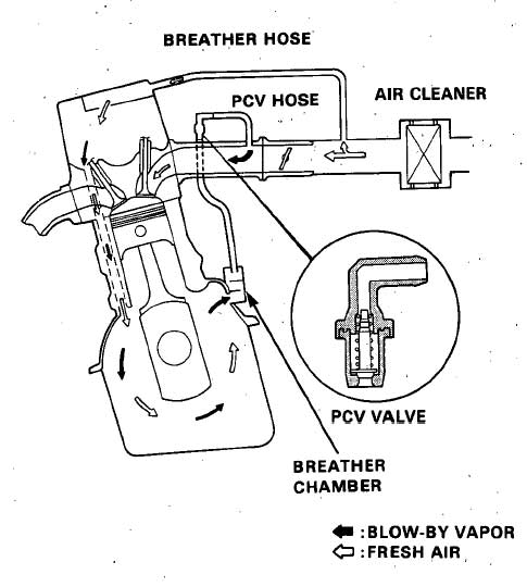
crankcase, fighting against the pressure. In a turbo application this system must be modified or it will not work. Before figuring out how to modify the system it is a good idea to see how the stock system works. Below is a diagram of the stock PCV system:

As you can see the system begins in the intake pipe where air enters a hose that is attached to a barbed fitting on the valve cover. It is important to realize that the fitting on the valve cover is the PCV system inlet, air goes into the valve cover here. The air flows down through the head and into the crankcase. Once in the crankcase the air will pick up oil vapor from the oil being slung around at high velocity by the rotating assembly. The air then flows through the 'breather chamber' which is the black box you see on the back of the block under the intake manifold. The breather chamber has baffling in it that separates out some of the oil vapor and allows it to drain back into the crankcase. A hose connects the breather chamber to the PCV valve. The PCV valve is a one way valve that is open when a vacuum pressure is applied to the top of the valve. The PCV valve is connected to the intake manifold with a hose. The intake manifold exerts a vacuum pressure on the entire system. The PCV system is a closed vacuum circuit with pressure being exerted on one end and vacuum

on the other. This allows any positive pressure in the crankcase to be vented.

The problem when a turbocharger is added is that the intake pipe and intake manifold become pressurized. If the fitting on the valve cover is still connected to the pressurized intake pipe it will pressurize the crankcase too. At the same time, the PCV valve will close when pressure is exerted on the top half of the valve, sealing the crankcase. If no modifications are made to the system a pressurized and sealed crankcase will occur when the boost kicks in, this is the worst possible time to have a sealed and pressurized crankcase.


Above is an example for PCV system . For Cam tak pro ( CAMPRO ) , No valve available . Proton uses to have the driver side breather hole into extreme small size , so the air won't go too fast and effect idling speed stability . Once bolt on turbo , PCV valve needed at driver size breather . This valve will block all air flow if no vacuum ( Negative pressure ) present or positive pressure present . Another place is petrol tank ventilation valve . Campro got a petrol tank ventilation valve plug at throttle body . This valve uses to work all time once engine running . So pcv valve also needed there , to prevent boost leak to petrol tank . This has been practiced when i had installed e-turbo last time .

Friday, March 21, 2008

TURBO MANIFOLD FOR MY CAM TAK PRO

IT is the shape of my turbo manifold later . This is called log type manifold . It is a good and cheap turbo manifold that can get if compare to turbular type turbo manifold . Since running low boost , this type of manifold is good to use .

Wednesday, March 19, 2008

Turbo a NA engine

To build a turbo engine is cost for car maker . A turbo car uses to sell double the price of a NA ( natural aspirated ) car . NA engine is far more easy to build and maintain , but the output power and performance way far poor than a turbo engine .
Especially for youngster and some others whom performance minder , NA engine output power is under their expectation . Even they got the honda v-tec B16A type R , they still want to bolt on turbo . They can't find any excitement or wooh from that honda popular v-tec or screaming engine . Nowadays market full with engine which build to last and fuel save . Everybody struggling with petrol price hike . Everybody looking for fuel save , but then they also demand good performance from fuel save machine which is NA engine . That is never happen . In the end , they can't stand with poor performance of their so called " fuel save " machine . They looking for workshop that able to help them to boost some power of their " fuel save " machine . Come to workshop , mechanic will alway say you want immediate power and bolt on turbo is the choice . When the mechanic quote them price of turbo kit , they will faint with the figure . For bolt on turbo , easily touch RM7000 . Woh that figure is really make them to die heart and never think about immediate power again . In fact they never think , they have spent on those small upgrade nearly touch rm5000 - rm6000 in many months ago . They still can't get the expected performance . In the end , they give up to modify their " fuel save" machine and let it be .

If you want your fuel save machine or NA engine to boost more power , pls save more to bolt on a turbo . The price that you pay is far more worth it than you spend on those look cheap and not really improve performance . Although offered price of a turbo kit is 4 figure , it can satisfy you .

Next we will take about how to turbocharge a natural aspirated engine .

Tuesday, March 18, 2008

Turbo my proton 1.6liter " cam tak pro " [ CAMPRO]


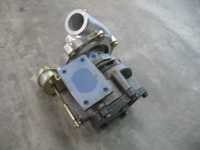
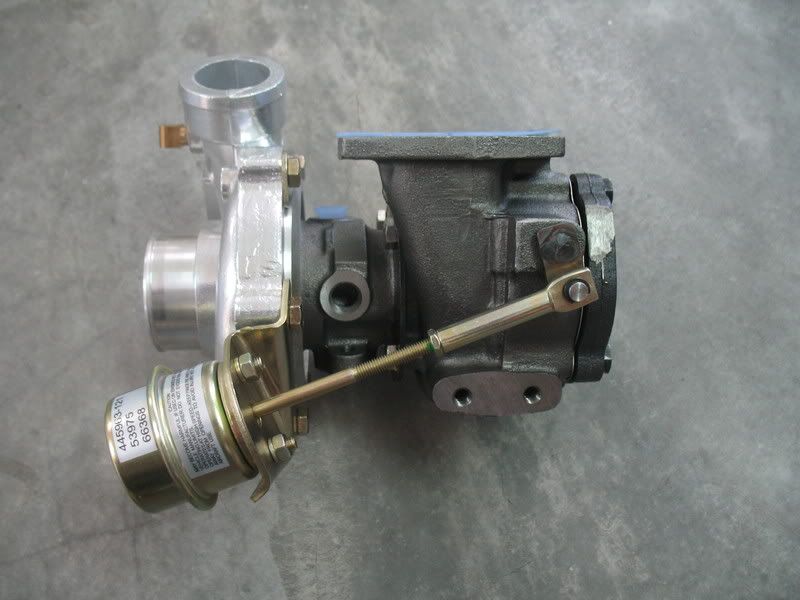
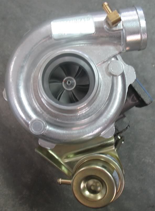
Below is my turbocharger unit ....

1) start to fabricate log type turbo manifold . After the project go smooth will switch to turbular type header . Estimate rm600
2) Source for oil feed fitting and oil drain fitting Rm100 . Steel braided hose as well .. Expensive item ... 2 hoses cost Rm200
3) If want to run water cooling , need another 2 steel braided hose Rm150 again
4) Will use evo silent blow off ( free )
5) all boost piping and intercooler ( will mount behind right side bumper ) estimated Rm500
6) run 2 x 250 cc extra injectors . rm100
7) fuel line for extra injector rm100
8) need to add one more unichip turbo module rm450
9) silicone hose reducer rm60 , 4 x 2.5" rm250 . clip x 10 .... rm50
10) down pipe rm60
11) unichip Rm2199
12) Gt2510 turbo Rm1800 ( new ) .


initial target boost 0.4 bars Tongue If everything goes well , will go 0.5 bars with double metal gasket.

all is money .. pengsan

Will update stage by stage .. start with turbo manifold first . Turbo manifold will complete by next month .